GCP Cloud Labs - Lab Seven
Publishing an internal application in a GCP environment. In this lab you learn how to deploy an application from GKE or Cloud Run to an internal-only environment, or publish it through Apigee.
Publishing an Internal Application
In this lab you can acquire knowledge and practice the following topics:
-
Working with Kubernetes in general and GKE in particular.
-
Cloud Run.
-
Private Service Connect.
-
GCP Load Balancer.
-
Apigee.
Introduction:
After learning how to deploy an application in different environments, we’ll see how to publish it externally in indirect ways. Later we’ll use this knowledge to work with intermediaries and segments in the publishing chain, to place protections.
To start, we’ll deepen our knowledge a bit about calling a Kubernetes service and its settings, and then touch briefly on the world of Apigee.
Internal Connection to a Service in GKE:
In the previous lab we deployed the game on a Kubernetes cluster in GKE, and immediately exposed the service to the world with an external address. In similar cases, applications, APIs, FrontEnds of dynamic websites and more are placed on the cluster. In such a situation we want to protect the service as much as possible from attacks. Therefore we won’t expose the service directly to the internet, but will place it behind filters and security services that know how to detect attacks and filter traffic, and then forward clean requests to the service.
When you want to access something running in a cluster, you create what is called a Service. This is a kind of internal Load Balancer for a Kubernetes cluster. It takes an address in the range we defined for Services, and from it distributes traffic to the various Pods that exist in the deployment.
When we set up the service in the previous lab, we defined the Service as Type Load Balancer. This type uses the basic Service component, and creates on top of it a Load Balancer that forwards requests to it. By default, this will be an External Load Balancer. If we define the Service as Type Cluster IP, it will receive an internal-only address from the Services range.
First we’ll define a new Service as a Cluster IP.
Like most things in Kubernetes, we’ll define it using a YAML file.
Editing YAML:
We’ll open Notepad++ or some code editor and insert the following content:
apiVersion: v1
kind: Service
metadata:
  name: breakbricks-clusterip
  namespace: breakbricks
spec:
  selector:
    app: breakbricks
  type: ClusterIP
  ports:
  - protocol: TCP
    port: 80
Explanation:
Let’s pause on the sections to understand the YAML structure that defines something in Kubernetes:
-
There will always be an apiVersion. Usually it will be v1. To change it you need a specific feature that you’re looking for in another version.
-
Kind - determines what type of item to associate the settings with. Here it’s Service, elsewhere it will be Deployment, ReplicaSet, ServiceAccount or NameSpace. And there are many more.
-
Metadata - required. Always contains the name and the namespace in which the item resides. Sometimes also labels called annotations. These contain category associations. We’ll get to that later.
-
Spec - an area that contains the actual setting items.
Placement:
So we have a YAML format for a Service that should match the Deployment we deployed in the cluster, and we’ve defined it as ClusterIP type. Now to apply these settings we’ll connect via SSH to the kube-management server set up in the previous lab, and there enter the command:
nano clusterip.yamlPaste the content there, save and exit. Then enter the following command:
kubectl apply -f clusterip.yamlAnd now let’s see what we got:
kubectl get services -n beakbricksWe’ll get something that looks like this:
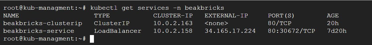 Displaying services in Kubernetes
-
Cluster IP, as its name implies. This is an internal address within the Cluster, and attempts to access the address from the kube-management server or any other server will not receive a response. All of this is because there is no routing or association in the VPC toward that address, and it is not exposed or published by the Cluster to the network it sits in. This is an internal-only address intended for services to communicate with each other within the cluster.
-
When configuring an Internal Endpoint for the cluster (security settings, for Control Plane), that address constitutes a ClusterIP type service. That address alone will be accessible to the VPC in which the cluster was placed. This accessibility is enabled because GCP creates Peering between the internal network where the Control Plane resides, and the VPC where the cluster’s machines are located. The peering enables communication and defines routing between the networks.
LoadBalancer:
When the deployment was created, we chose to expose the application using a LoadBalancer type service. But it created an external IP address for us. What happens behind the scenes is that a service is created within the cluster, and outside the cluster an LB is created with an external address, pointing directly to each machine in the cluster.
If we want to create a LoadBalancer with internal-only access, it will work slightly differently, and we have two ways to do it.
Default:
We’ll create a YAML Manifest for the service in the following format:
apiVersion: v1
kind: Service
metadata:
  name: internal
  namespace: breakbricks
  annotations:
    networking.gke.io/load-balancer-type: "Internal"
spec:
  selector:
    app: breakbricks
  type: LoadBalancer
  ports:
  - protocol: TCP
    port: 80
You can see that this time under type we changed the type, and there is also an annotation that says it is internal only.
In this configuration an LB will be created that forwards requests to the Instance Group in each zone where the cluster’s machines reside.
We’ll use the following command:
nano internalPaste the YAML content there. Save and exit.
Then enter the following command:
kubectl apply -f internalAnd immediately the service is created.
If we enter a command to display the list of services, or even give the details of that specific service, we’ll see that the external address is pending. But within a few minutes it will finish creating the LB and there will be an address there too. But an internal address in the same subnet where the cluster’s machines and kube-management reside.
We can verify the application’s availability by using telnet to that address on port 80. Anyone who really wants to verify end-to-end can set up an Ubuntu desktop machine on that same network as explained in the fourth lab. From that machine, browse in a browser to that address and verify that the application loads.
GKE subsetting:
Kubernetes Engine >> Clusters >> app >> DETAILS >> Networking >> Subsetting for L4 Internal Load Balancers.
Go to the cluster settings in the DETAILS tab, scroll down to the networks category and enable the above setting.
Now we’ll create an additional service with a similar YAML, only giving it the name sub:
 apiVersion: v1
kind: Service
metadata:
  name: sub
  namespace: breakbricks
  annotations:
    networking.gke.io/load-balancer-type: "Internal"
spec:
  selector:
    app: breakbricks
  type: LoadBalancer
  ports:
  - protocol: TCP
    port: 80
Then we’ll enter it into a file, activate using apply, etc. After a few minutes we’ll see a new LB was created, this time it points to the application through a Network Endpoint Group.
Ingress:
Ingress constitutes a more complex setup, that creates a gateway and routing from outside the cluster to that ClusterIP. When we create an Ingress, a Network Endpoint Group will be created in each zone. Each one points to machines deployed in that zone for the cluster.
The main differences between Ingress and LB are two:
-
LB creates routing at Layer 4. That is, what is called a Network Load Balancer. While Ingress creates routing at Layer 7. What is called an Application Load Balancer.
-
LB points to IP addresses of the target application, while Ingress points to a Service as the target. That Service can also be a ClusterIP.
The first difference leads to the second and stems from the purpose of the second - Ingress is designed to be the main gateway for a complete application composed of several services. Since it is an Application Load Balancer it can route requests to each service according to rules that only work at Layer 7, such as routing to a service based on path, header, etc.
Application Load Balancer works of course in a somewhat different way from Network Load Balancer. To create one you need to add an address range for proxies to that VPC.
Creating a Proxy Subnet:
-
Open the main menu.
-
VPC network > VPC networks >> app.
-
After entering the settings of the app VPC, switch to the SUBNETS tab.
-
Click ADD SUBNET.
-
Give the name app-proxy, choose Region me-west1, mark Regional Managed Proxy, then below give the range - 10.0.3.0/24.
-
Click ADD.
We’ll create a YAML Manifest:
apiVersion: networking.k8s.io/v1
kind: Ingress
metadata:
  name: ing
  namespace: breakbricks
  annotations:
    kubernetes.io/ingress.class: "gce-internal"
spec:
  defaultBackend:
    service:
      name: breakbricks-clusterip
      port:
        number: 80
Note that this time the apiVersion section has changed, and in the annotation section we’re careful about the value that will create an internal address.
You can also note that in the spec class there is a typical Application Load Balancer reference, that defines a default target. And the target in the case of Ingress is a Service. In our case, we’re pointing to the ClusterIP type one we created earlier.
Routing by Service:
Of course, we can add rules by which that Application Load Balancer routes requests. This can look like this:
apiVersion: networking.k8s.io/v1
kind: Ingress
metadata:
  name: ingress
  namespace: breakbricks
  annotations:
    kubernetes.io/ingress.class: "gce-internal"
spec:
  defaultBackend:
    service:
      name: breakbricks-clusterip
      port:
        number: 80
  rules:
  - host: app.example.com
    http:
      paths:
      - path: /index.html
        pathType: ImplementationSpecific
        backend:
          service:
            name: internal
            port:
              number: 80
      - path: /differentgame/
        pathType: Prefix
        backend:
          service:
            name: internal
            port:
              number: 80
As can be seen, here routing rules were added on top of the default. All the rules refer to the case where a request contains a specific Hostname, and two path options. You can create more rules for a different Hostname and add to the YAML. There is also a pathType of Exact which means the condition will only apply if the entire Path that passed in the request matches what was defined in the rule.
If we enter this content into a file named ing and then enter the command:
Kubectl apply -f ingThat Ingress will be created immediately, though it will take a few minutes to create all the routes and receive an IP address.
Internal Publishing of Cloud Run:
In the previous lab we published a service from GKE directly to the outside. Now we’ve learned to publish it internally. So now we’ll learn how to publish a service from Cloud Run internally.
The difference between Cloud Run and GKE is that GKE is not entirely Serverless. Certainly in the configuration we worked with, we see in our network the machines on which the cluster operates and we manage its network in our environment. Cloud Run on the other hand is a full cloud service. We don’t communicate with it through a specific IP address or a range that exists in our network, but through Google’s management API, and the service is consumed through a URL that points to Google’s general network. Not something we control.
And yet we’ll often want to place an internal service using Cloud Run. We might even want to place it internally and publish it in a controlled manner through means we manage. But that’s for a later stage.
Now we’ll take the service we published earlier and update it to an internal configuration. Anyone who deleted it will rebuild it with the internal publishing settings.
Editing an Existing Service:
-
Go to Cloud Run, switch to the Services tab and enter the breakbricks service.
-
At the top left we’ll see the service name. If everything is fine, next to it will be a green tag with a V. Next to it is the location and a link to the service. Below are tabs, switch to the NETWORKING tab.
-
In the Ingress Control box check Internal. Anyone setting up the service from scratch sets it up as in the instructions from the sixth lab, just in the Ingress Control section marks Internal.
-
Now a checkbox will appear that can enable traffic from an External Load Balancer. Don’t check it.
-
Click SAVE.
- The VPC box refers to traffic going out from Cloud Run toward our internal network environment. We’ll touch on this in one of the next labs where we’ll point from Cloud Run to an internal address.
Internal Access:
-
In the GCP main menu: Network services >> Load balancing.
-
Click CREATE LOAD BALANCER at the top.
-
Choose the left box - Application Load Balancer. Click START CONFIGURATION there at the bottom.
-
In the upper section we have a choice - Internet facing or internal only. Choose the lower option of Only between my VMs or serverless services.
-
In the lower section choose the lower option - Regional internal Application Load Balancer.
-
Click CONTINUE.
-
Now the main settings page of the Load Balancer opens. Give it the name - breackbricks-run.
-
Place it in the Tel Aviv region and in the app network.
-
On the right side there is Backend configuration. Click on the menu there and click CREATE BACKEND SERVICE.
-
In the window that pops up on the right, give it the name - breakbricks-run.
-
Backend type - choose Serverless network endpoint group.
-
Then scroll further down and under New backend click the menu and click CREATE SERVERLESS NETWORK ENDPOINT GROUP.
-
Give it again the name breakbricks-run.
-
Below there is Select service. There choose the service we set up - breakbricks.
-
Click CREATE. Click CREATE again. Then click OK.
-
In the middle column we see that Frontend configuration remains to be defined. Click there and go to the Frontend settings.
-
There is no need to change the protocol. Leave it as HTTP.
-
Under Subnetwork choose main.
-
Leave the port at 80.
-
Under IP address choose Ephemeral (Custom). This means the address is not locked, and will remain occupied only as long as the Frontend definition exists. Once we delete this Frontend (which is actually a Forwarding rule), the address will return to the pool and we can use it for any machine or other thing on the network. Then in the address field put - 10.0.1.150.
-
Click CREATE.
It will take a few minutes for everything to come up, and then whoever set up Ubuntu-desktop will be able to see that if they browse to that address, they receive the game running in Cloud Run.
Apigee:
Apigee is a service that enables API management and publishing them to the world in a secure manner. This includes proxy configuration and several protection components that can be applied along the way.
The Apigee environment as we’ll use it (known as Apigee X) is a managed service running on Kubernetes in a project and network managed entirely by GCP. We get access to the service’s features and not its infrastructure, and pass through it using VPC Peering.
Setting Up Apigee:
Network Preparation:
-
In the main menu go to VPC network and enter the settings of the app network.
-
Switch to the VPC NETWORK PEERING tab.
-
Click PRIVATE SERVICES ACCESS.
-
Below there are two tabs. We’re on ALLOCATED IP RANGES FOR SERVICES. Click ALLOCATE IP RANGE.
-
In the popup give it the name apigee peering and the range - 192.168.8.0/21.
-
Click ALLOCATE.
Creating the Apigee Environment:
In the main menu on the side, scroll down to the INTEGRATION SERVICES category and click on Apigee, or type in the search bar at the top.
On the Welcome to Apigee API management page that opens, check the upper left box. If there is a link there to try Apigee free for two months, that’s preferable. Because this is a product that costs a minimum of 300 dollars per month and will devour the budget given to you for experimentation. If not, click CUSTOMIZE YOUR SETUP.
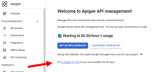 Free trial with Apigee
-
On the page that opens, a list of APIs will appear, and we’ll need to confirm enabling them if they’re not yet enabled. Click ENABLE APIS.
-
Now we’ll edit the networking. Click EDIT.
-
Choose Authorized network. This is the network from which there will be access to Apigee via Peering. Choose the app network.
-
Under Allocate peering ranges you need to define ranges for sharing between our network (app) and Apigee. Mark Select one or more existing IP ranges or create a new one, then in the menu choose the apigee-peering range we created earlier.
-
Under Select runtime IP range mark custom then choose ranges for the system. Choose 10.200.4.0 for prefix range 22, and also 10.100.0.16 for prefix range 28. Pay attention to the addresses, they indicate how many addresses those networks occupy.
-
Click ALLOCATE AND CONNECT.
-
Click NEXT.
-
Now in Configure hosting and encryption click EDIT.
-
In Control Plane choose Analytics region - me-west1 and then click CONFIRM.
-
In Runtime choose Runtime hosting region - me-west1, then click DONE.
-
Click NEXT.
-
Click SUBMIT.
Notes:
-
When needing to define address ranges, you can click Automatically allocate IP range because we’re in a lab environment. But anyone setting this up in an extensive enterprise environment needs to be careful to choose ranges that won’t conflict in communication with other networks. If setting up Apigee in an isolated configuration, there’s no problem with this and the networks won’t conflict. Later we’ll understand the meaning of isolation.
-
In a lab environment we don’t have this problem, but in an enterprise environment we might need to exclude the project from various Organization Policies that will stop the process. For example - one that enforces Peering to specific networks will prevent the process due to creating Peering to Apigee’s network which is in a Google project. One that enforces creating an External Load Balancer will stop the process, as will one that restricts creating resources in a specific project - because the Control-Plane itself sits in America. Pay attention beforehand to avoid stopping the process. Otherwise there will be resources created and the process will get stuck if you don’t know what to clean up to allow a Retry.
Getting Familiar with Service Components:
So what does the setup that was created contain? That is, what can be seen in our environment?
-
An external LB, with an external address. Can be found under NETWORK SERVICES >> Load balancing.
-
Its target - NEG, can be found under Compute Engine >> Network endpoint groups.
-
An Instance that is a black box from our perspective that we can barely configure anything in. Can be found in the Apigee menu under Instances.
Later we’ll create more settings in our environment that we can use to properly link our services with Apigee.
Anyone who for various reasons wants to create an internal Apigee that is not accessible from outside, can delete that External Load Balancer and create an Internal Application Load Balancer in its place, that routes to the same NEG.
Different Environments:
In the Apigee menu scroll down to the Management category and click on Environments.
You can see that by default a test environment was created. It’s called env-test or eval.
-
When placing a Proxy, it is placed under a specific environment.
-
A Proxy can be placed in more than one environment.
-
Each environment we set up costs money separately, even before placing a single setting in it.
-
Each environment can be a member of multiple environment groups.
We’ll see at the top of the page that there’s another tab, for environment groups. Let’s go there.
Currently there is only the default group. And it contains the Hostname that was created by default. Usually that Hostname constitutes that same external IP address that the External LB received, combined with the nip.io suffix.
Click on the three dots on the right under Action, then Edit.
There under Hostnames we’ll cut what’s there and paste it aside in Notepad, then place there the following name - breakbricks.example
Then click UPDATE.
What will happen now is that any request arriving at Apigee with a different Hostname will be ignored. We’ll dwell on this a bit more later.
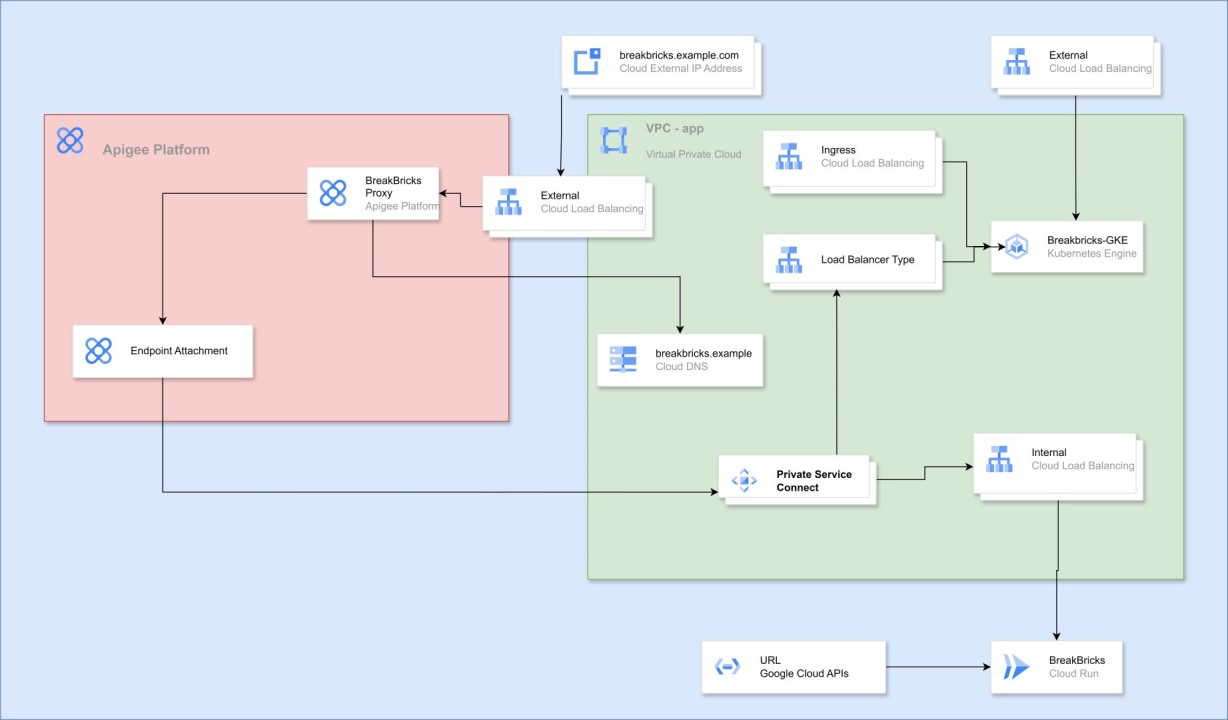
Publishing an Application Through Apigee:
To publish an application through Apigee, several things need to be configured in different places.
As explained above, Apigee sets up resources in Google’s project. To link the proxy in Apigee’s environment to our service, we’ll need some kind of bridge. The bridge will be accomplished by adding a leg and access point to the LB that leads to the service. That access point will be created as a NAT Proxy within a small Subnet we’ll set up for this purpose, and Apigee will have access to that Subnet.
Publishing a Service:
-
Network services >> Private Service Connect.
-
We’ll see at the top of the page that there are several tabs. We’ll go to PUBLISHED SERVICES.
-
Click PUBLISH SERVICE.
-
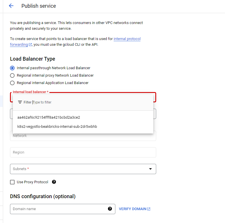
Now we can choose the type of LB to which Apigee will connect. If we mark the first one, we can use the services we published earlier of the Load Balancer type. If we mark the third one, we can use what was created when we defined Ingress. In the lab environment there will be nothing available in the middle option. Leave the first option marked.
-
When we click on the menu marked as Internal load balancer, we’ll see two options that are almost unclear (screenshot below). In fact, these are the names given to the Load Balancers we created from Kubectl. To identify which is which, you can go to GKE, under Workloads enter our application, and there at the bottom find the Services we published and check in each one’s settings which is which. I’ll choose the one pointing to internal-sub. I’ll click on the service name at the bottom of the page, and then the service’s page will open. There under Load Balancer the name I need to choose in the menu will appear.
-
Under Service name give it the name breakbricks.
-
Under Subnets we’ll need to choose an address range to serve as NAT Proxy for the LB. Click RESERVE NEW SUBNET.
-
In the window that pops up give the Subnet the name breakbricks-psc, and the address range 10.0.250.0/29. No larger range is needed because only Apigee connects there. Then click ADD. - Anyone publishing a service for another purpose where there are many sources connecting to the service from various networks and projects, will need to allocate a larger range.
-
After some time that range of addresses will be created, will appear under Subnets and we can click OK.
-
Verify that the Enable connection reconciliation box is checked at the bottom, which allows us to immediately cancel approved connections.
-
Click ADD SERVICE.
 Publishing a service
Consuming a Service in Apigee:
Consuming a Service in Apigee:
Now we’ll need to connect the Apigee environment to the service we published.
-
In the Apigee menu go to Endpoint Attachments.
-
Click CREATE at the top.
-
On the page that opens give the name - breakbricks.
-
Under GCP Project ID enter the name of the project where the service was published.
-
Then we’ll see a Service Attachment menu, where we can choose from the services published in the project we wrote in the previous section. In our case, choose breakbricks.
-
Click NEXT.
-
Mark the I understand box and click CREATE.
Approving the Connection Between Publisher and Consumer:
After some time we’ll see the connection appearing in our list, but it’s in Pending status. To complete the process go to the service we published earlier under Published Services. There we’ll see below Connected projects and the connection we created from the Apigee side, in Pending status.
We can mark the checkbox on the left and buttons will appear above the list,
We can click on the three dots on the right of the item,
And we can enter the connection’s settings.
In the end, you need to click Accept Project. Right now we’re not expecting many connections from that Apigee project, so the default number that appears - 10, is fine.
After a short time the connection will appear as Accepted on both sides.
See on the Apigee side that the connection received an IP address under Host. Usually something like 7.0.8… Write it aside and save the address, because this is the address at which Apigee calls that service attached to it.
Creating a Proxy:
-
In the Apigee menu click on API proxies.
-
At the top of the page click CREATE.
-
Give the name breakbricks.
-
Verify that the base path field contains content like the name we chose.
-
Under target delete what’s there and put the address - http://game.breakbricks.example
-
Click NEXT.
-
Under Deployment environments choose the only environment we have - test-env.
-
Click CREATE.
In fact, we could have put an IP address under the connection target address. But in many cases we’ll want to point to a target that is a DNS address, especially if that LB we’re pointing to receives requests via HTTPS and therefore needs to receive requests with the appropriate DNS. Therefore we’ll learn how to do this with DNS.
Creating a Private DNS Zone:
In the project where Apigee exists:
-
Network Services >> Cloud DNS.
-
If we get a message that Data could not be loaded, click CONTINUE and on the page that opens enable the Cloud DNS API.
-
On the Cloud DNS page click CREATE ZONE at the top.
-
Zone type - choose Private.
-
Under Zone name put the domain we gave earlier to the proxy target - breakbricks.example. Since the name cannot contain a period, replace the middle period with a hyphen.
-
Under DNS name paste the same thing without replacing anything - breakbricks.example.
-
Under Networks we’ll need to choose which networks that zone will be available for. Choose the network adjacent to which we set up Apigee. In our case this will be the app network.
-
Click CREATE.
-
On the Zone page that opens, we’ll see that basic NS and SOA records were created for us. Above them click ADD STANDARD.
-
In the DNS name field write game. Combined with the domain given to this Zone, this will form the DNS we gave to the proxy target we set up.
-
In the IPv4 Address field put the address of that Endpoint Attachment we set up earlier and noted aside - 7.0.8… whatever we received there.
DNS Peering:
Now requests to the address game.breakbricks.example from the app network receive a Resolve of that IP address of the breakbricks Endpoint Attachment.
But Apigee still doesn’t know how to receive that Resolve. For that one more step is needed.
We’ll open Cloud Shell and enter the following command:
gcloud services peered-dns-domains create breakbricks-example —network app —dns-suffix game.breakbricks.example. —project mobile-app-yosi
Now that DNS Zone gives answers not only to the app network, but to all networks that have peering with it. Including and especially - the network where our Apigee environment resides.
Accessing the Service from the World:
On our computer, enter a record in the hosts file:
34.128.154.189 breakbricks.example
Under that IP address, put the external address that the Apigee External LB received. So that requests from this computer to breakbricks.example, will reach our Apigee.
Now you can enter in the browser the address https://breakbricks.example/breakbricks and receive our game through Apigee.
Of course we’ll get a certificate warning. This is because we didn’t upload to the External LB an appropriate certificate for the breakbricks.example domain. Currently there is the default certificate that it received from Google for the DNS containing the initial Hostname we saw earlier. When setting up Apigee in an enterprise/business environment, we’ll have a proper DNS of the organization’s domain, pointing to the IP address of that External IP.
Then we’ll configure in the Environment Group to accept requests (only) under that name, and upload to the LB an appropriate certificate for that name.
Notes:
-
You can publish the Cloud Run service externally in the same way through a proxy pointing to address 10.0.1.150, or to a DNS address pointing to that name. In enterprise environments in most cases the proxy won’t point there directly, you first need to publish the service in Private Service Connect and then as an Endpoint Attachment. The proxy will point to the Endpoint Attachment. It’s advisable to give it a DNS address as we practiced earlier.
-
A call to the proxy we uploaded to Apigee will include as Hostname a name defined in the Environment Group that the environment hosting that proxy is a member of. After the name comes what was defined in the proxy as the base path. After that comes the path through which you call that file, API, or specific function in that API. It looks like this: https://hostname/basepath/target
-
If we placed as the proxy target a whole server, or a basic path after which there are many options, we’ll need to continue after that proxy basepath everything that needed to continue after what was defined in target. For example, if there’s a service accessed on the internal network at the following address: https://localserver.local/v1/anothergame/healthcheck and suppose we defined for the proxy as target the address - https://localserver.local/v1 then external access to the service will need to be: https://breakbricks.example/breakbricks/anothergame/healthcheck
-
When more Hostname names are defined under the same group (Environment Group) or in other groups, Apigee will only accept the names defined for it in the groups it has.
-
Sometimes the environment is a member of several groups, with each group having a different name defined. Then it will be possible to reach the proxy target with any of the names defined for the groups in which that environment is a member.
-
If we deployed the proxy in multiple environments, the proxy will be accessible from any name linked to those environments according to the previous rule.
-
In summary - Apigee accepts requests as an Application Load Balancer and routes the requests to the various environments and proxies according to Hostname and also according to path.