GCP Lab - Hub and Spoke Topology
A lab for practicing networking and Image configuration in the GCP cloud environment. In this lab you can learn and practice creating Hub and Spoke topology, as well as creating and importing Images to the cloud environment.
Hub and Spoke Topology
Introduction:
This lab can stand on its own for those who already have familiarity with the GCP cloud environment. Those who encounter unfamiliar concepts or instructions that aren’t clear on how to perform can start from the first lab in the series. All the labs were published as articles on my LinkedIn and are built in stages. There is no topic in this lab that isn’t explained, that wasn’t raised and explained previously. In the first lab in the series, 4 networks were created across two different projects, and it was explained how to create a network structure between the three networks established in the first project. The primary goal of this lab is to unite all four of these networks into one network structure in a hub and spoke configuration.
The remaining topics learned in this lab are acquired as part of the stations along the way to achieving this goal.
In this lab you can acquire knowledge and practice the following topics:
-
Importing custom and unique operating systems into the GCP environment.
-
Installing PfSense Firewall.
-
Routing in GCP networks.
-
Creating a network in hub and spoke - Star Topology (or Hub and Spoke).
On the Agenda:
In previous labs we learned how to create virtual machines in the GCP environment. We can use the management panel via browser or the command interface to create machines from the catalog GCP offers. But sometimes we want to build a machine from an operating system not on the list.
Here we’ll learn two methods to import an operating system not on the list.
For one of the tasks later, we’ll need to use a browser from a machine located inside our cloud network. Since Windows machines cannot be installed in an account that’s in the trial period without billing enabled, we’ll use a Linux operating system with a GUI.
The existing GCP list doesn’t include Linux with a GUI. Of course, a GUI environment can be installed on a Linux server created from the list, but one of the goals in this lab is to import an operating system not on the list.
The first method we’ll learn - is through creating an OVA file.
Creating an OVA of a Machine in Oracle VirtualBox:
Go to the Ubuntu website to download Ubuntu Desktop.
Creating the Machine:
Clicking the download button will save an ISO to the downloads folder on the computer.
Now we’ll create an OVA file of the machine using Oracle VirtualBox, which is a virtualization environment that can be installed free on your computer.
Open VirtualBox (install if not installed), then from the menu - Machine >> New.
In the window that opens, select a name - ubuntu-desktop, a location to store the virtual machine files, and select the ISO file we downloaded. The software will know on its own that this is a Linux distribution. If not, mark it. Next.
Now select the user and password we’ll connect with to the system after installation.
Resources need to be allocated to the virtual machine. To give a quick installation, allocate as many resources as possible (leave what’s needed so the physical computer keeps working). Next.
20GB disk, Next, Finish.
The machine will start booting, then the installation screens will appear. Complete the installation until the system comes up.
Exporting the Machine:
At the bottom of the window, right-click on the disk icon and in the pop-up menu, select to remove the disk from the machine (the ISO).
In the Machine menu, select Shutdown.
When the machine is off, return again to the menu: Machine >> Export to OCI.
Verify the format is version 1.0 - Open Virtualization Format.
Select a location to export the OVA file to, skip the MAC addresses, mark writing a Manifest file. Next.
Now there’s an Appliance settings window. You can skip the sound card and USB controller. Click Finish.
We have an OVA file.
Creating a Storage Bucket for Operating System Files:
To import the operating system, we’ll need the OVA file to sit inside the GCP environment. We’ll use a storage bucket.
In the GCP management menu (three lines) go to Cloud Storage, Buckets. On the page that opens, click CREATE at the top.
Give a unique name - say, yos-pfsense. Continue.
Choose Region - select the Tel Aviv region: me-west1.
Then click CREATE.
A confirmation panel will pop up - confirm without changing. The bucket is created and its page opens.
Now we want to upload the OVA there. There’s an Upload Files button - upload and wait for it to finish.
When the file finishes uploading, click on it to enter its properties. There is a gsutil link. Copy it and paste in a notepad aside.
Service Account for Building a Machine from an OVA:
In the main menu go to APIs & Services >> Enable APIs & services.
Click ENABLE APIS AND SERVICES at the top, and on the page that opens search for cloud build api. Select when it appears in results, and on the page that opens click ENABLE.
- Cloud Build is used in a large portion of cases for building software packages, as well as Images for containers. In our case, it’s used to build an Image from the OVA.
The service account that performs the conversions, builds the Image and produces a working machine from it needs all kinds of permissions. Here we’ll define a dedicated service account for this operation, to avoid giving all these permissions to the default account that runs machines in the project.
Now we’ll create a service account for creating machines from OVA:
-
In the main menu go to IAM & Admin >> Service Accounts.
-
Click CREATE SERVICE ACCOUNT at the top.
-
Give it the name ova-builder, and click CREATE AND CONTINUE.
-
Now permissions need to be given to the account. Click the dropdown where it says Select a role.
-
Now we’ll need to give it permissions so it can access the bucket where the OVA is stored, to build a virtual machine from it and create a Token to authenticate the machine against GCP. In the window that opens, there is a search bar at the top. Enter each role name from the following list, and when it appears in filtering, select it. The following permissions need to be given:
-
Compute Admin
-
Service Account Token Creator
-
Service Account user
-
Compute Storage Admin
-
Storage Object Viewer
-
-
Click DONE.
Creating a Machine from the OVA:
To create a VM Instance from the OVA we uploaded to the bucket, we’ll use the CLI. Enter the following command in PowerShell ISE:
gcloud compute instances import "ubuntu-desktop" `
   --source-uri="gs://yos-pfsense/ubuntu-desktop.ova" `
   --no-address `
   --network="vpc-1" `
   --private-network-ip="10.0.10.50" `
   --subnet="subnet-1" `
   --zone="me-west1-a" `
   --project="yostest-1" `
   --log-location="gs://yos-pfsense/" `
   --service-account="ova-builder@yostest-1.iam.gserviceaccount.com" `
   --compute-service-account="ova-builder@yostest-1.iam.gserviceaccount.com" `
   --os="ubuntu-2204" `
--no-guest-environment -
Note there is a no-address flag here, meaning the machine won’t receive an external address. The machine will need an external address later, but I wanted to present this flag. You can omit it, or add an external address later.
-
Important to see there’s a no-guest-environment flag here that tells the system to build the machine as a BlackBox. That means a closed Appliance that GCP doesn’t manage internally and doesn’t bring up with its Ops Agent by default. The Ops Agent can be attempted to install later, but we won’t dwell on that.
It will take about an hour for the machine to come up, then go to the machine’s page and open its terminal by clicking CONNECT TO SERIAL CONSOLE.
Configuring the Machine:
When the terminal comes up (in the black screen, press Enter to display content), we’ll need to connect. Enter the user and password we set when creating the machine in VirtualBox.
But this user lacks Root permissions, so first we’ll need to grant them.
First connect as root. For that enter the command su, and when a password request appears, enter our user’s password.
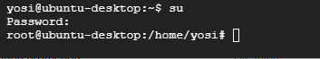 Switching to root user
Then add the user to the sudo group using the following command:
usermod -aG sudo yosiOf course, instead of yosi, each person enters the user they chose.
Once the command is received, enter the exit command twice. Once to exit the root user, and a second time to exit our user.
Then connect again with our user, and this time they have root permissions. So if they run a sudo command or press sudo -i, their password will pass the command successfully.
Connect to root user with the command sudo -i.
Now disable the machine’s internal firewall using the commands:
systemctl disable ufw.service
systemctl stop ufw.service
Normally it’s not advisable to completely disable the firewall, but we’re in a lab environment and want things to go more easily for us.
Connecting via External Address:
Go to the machine’s page in GCP, edit the machine settings and give it an external network address. No shutdown is needed.
Then install a tool that allows remote connection to the machine’s desktop.
In the machine’s CLI, enter the following commands:
wget https://dl.google.com/linux/direct/chrome-remote-desktop_current_amd64.deb
sudo apt-get install --assume-yes ./chrome-remote-desktop_current_amd64.deb
If the following error appears:
N: Download is performed unsandboxed as root as file '/root/chrome-remote-desktop_current_amd64.deb' couldn't be accessed by user '_apt'. - pkgAcquire::Run (13: Permission denied)Enter the following commands and redo the installation:
sudo chown -Rv _apt:root /var/cache/apt/archives/partial/
sudo chmod -Rv 700 /var/cache/apt/archives/partial/
After installation, restart the machine and reconnect with our user, without switching to root.
Minimize the terminal window, return to the browser and open the following link.
From here, configure the connection to the machine:
-
It will say “Set up another computer”. Click “Begin”.
-
We’ll be asked to install the software on the target computer, but we already installed it. Click “Next”.
-
We’ll receive a message to set a permission, click “Authorize”.
-
We’ll receive a code to paste in the terminal.
-
We’ll be asked to enter a PIN to authenticate our identity when connecting to the machine we set up in Chrome.
-
In the browser, navigate to the top right to “Remote Access”, and there we’ll see the machine we set up.
-
Enter the PIN to connect.
-
If a side window appears asking which type of Session to connect to, select Default.
-
Leave the connection to the machine open - we’ll return to it later.
Processing the pfsense Installation into a GCP Image:
Go to the downloads page of pfsense.
Select the installation as shown in the image, right-click DOWNLOAD and select “Copy link address”:
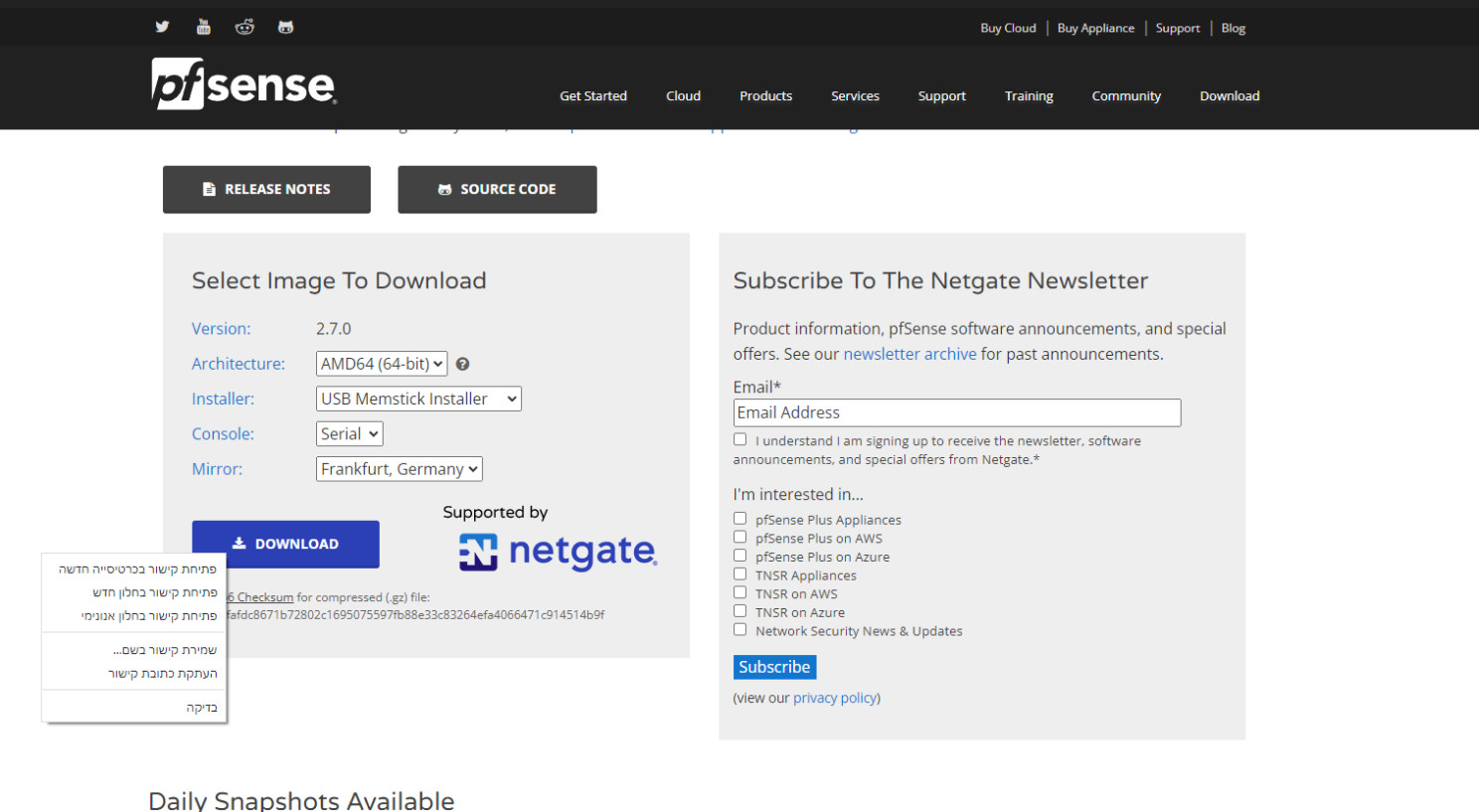 PFSense download page
Paste it aside in a notepad - it will look something like this:
https://frafiles.netgate.com/mirror/downloads/pfSense-CE-memstick-serial-2.7.0-RELEASE-amd64.img.gzReturn to the GCP management panel, and at the top right click Activate Cloud Shell:
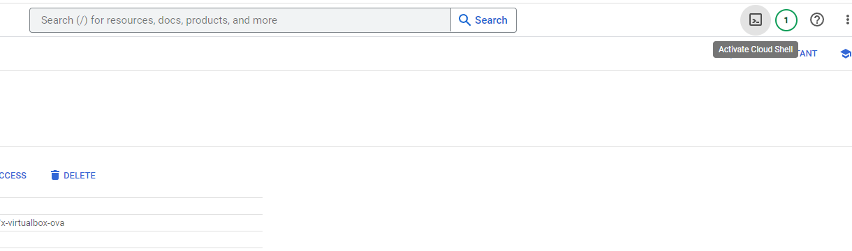 Activating Cloud Shell
That Cloud Shell is a Linux machine running behind the scenes, where users are given 5GB storage space to perform operations like the one we’ll perform now.
We’ll immediately see that such an operation from CloudShell is much faster than downloading the file to our computer and then uploading it to the cloud.
Download the pfsense installation to the machine, and immediately extract it to a file:
curl https://frafiles.netgate.com/mirror/downloads/pfSense-CE-memstick-serial-2.7.0-RELEASE-amd64.img.gz | gunzip > disk.rawImportant to remember:
- Name the internal disk disk.raw! GCP expects exactly that disk name, otherwise this won’t work when trying to convert it to an Image.
Then archive the file again in a format that GCP recognizes and allows creating Images from:
tar -Sczf pfSense-CE-memstick-serial-2.7.0-RELEASE-amd64.img.tar.gz disk.rawAnd now we can upload the file to the storage bucket we created earlier for operating system files:
gsutil cp pfSense-CE-memstick-serial-2.7.0-RELEASE-amd64.img.tar.gz gs://yos-pfsenseA message will immediately pop up asking whether we authorize the Cloud Shell to perform the operation on the bucket - click Authorize and wait for the operation to complete.
Creating the Image:
-
Compute Engine >> Images
-
Click CREATE IMAGE at the top.
-
Give it the name pfsense.
-
Source - Cloud Storage file.
-
In the field below, click BROWSE, select the bucket where we stored the file - in our case yos-pfsense, and there select the file we uploaded.
-
For location, choose Regional in the Tel Aviv region.
-
Click CREATE.
Creating a Machine from the Image:
-
Compute Engine >> VM Instances
-
CREATE INSTANCE
-
Give the name - pfsense
-
Verify the machine is created in the Tel Aviv region.
-
Machine type - e2-micro.
-
Change the machine’s Image from the default to the one we just created - in the Boot disk area click Change, switch to the CUSTOM IMAGES tab, select pfsense, choose a disk size of 10GB and click SELECT at the bottom.
-
Under Firewall mark Allow HTTPS traffic and also Allow HTTP traffic.
-
Under Networking, give the machine the network tag pfsense.
-
Check the Enable IP forwarding checkbox.
-
Give the machine two network cards - place the first in VPC-2 with address 10.0.20.150, place the second in vpc-1 with address 10.0.10.150. No external addresses.
-
Add an empty 10 GB disk and call it pfsense-boot.
-
Create the machine.
Installing pfsense on the Machine:
-
Enter the machine’s page.
-
Click CONNECT TO SERIAL CONSOLE.
-
When connected, there will be a black window. A single press of Enter will bring up the initial screen. From there mark the following options:
-
Accept
-
Install - Install pfSense
-
Auto (UFS) Guided UFS Disk Setup
-
Entire Disk
-
MBR
-
Finish
-
Commit
-
When asking to Reboot, shut down the machine and enter edit mode.
What just happened is that the Image we imported to GCP and used to bring up the machine isn’t actually a disk with an operating system, but more of an installation disk. When the system came up using it, it performed the installation on the additional disk.
Now we’ll need to remove the disk containing the Image - which as mentioned is essentially an installation disk - and bring up the machine with only the second disk as the system disk, since the operating system is installed on it.
Bringing Up the Machine:
-
Click Edit to edit the machine.
-
In the edit page scroll down to Storage, and click the X next to the second disk (pfsense-boot). This will remove it from the machine.
-
Click DETACH BOOT DISK to also remove the disk with the Image from the machine.
-
Now click SAVE.
-
Click EDIT again.
-
Scroll down to Storage and there click ATTACH BOOT DISK.
-
In the window that opens, select the right tab - Existing disk.
-
Select the pfsense-boot disk.
-
Save the changes and start the machine.
Configuring the Network Card:
-
When the machine comes up, open the Serial Console again.
-
Press Enter to get a Prompt.
-
We’ll be asked to choose an Interface for an external network. Since we only created network card 1, type vtnet0. Enter.
-
Then we’ll be asked to choose an Interface for an internal network, or just press Enter to skip. Press Enter.
-
Press y to confirm, Enter.
-
The system will tell us it’s configuring the external network, and stay that way without moving. Don’t worry. Give it 5-10 minutes, then go to the machine’s page and click RESET to restart the machine.
-
It will ask to enter a name for an external network card - type vtnet1.
-
It will ask to enter a name for an internal network card - type vtnet0.
-
Press y to confirm.
-
An options menu will appear. Press 2 to edit a network card.
-
Press 2 to edit the LAN network card.
-
Press y to confirm a LAN address via DHCP - meaning the machine’s internal setting will receive the address we gave it in GCP.
-
Press n to refuse to configure IPv6 with DHCP.
-
Press Enter to skip IPv6 settings.
-
Press n to not revert to http as the protocol for Web-based settings.
-
Press Enter to continue.
-
A brief summary of the operations being performed will appear, then press Enter to confirm.
Connecting to the pfsense Management Panel:
Return to the browser window through which the desktop of the ubuntu-desktop machine is open. From here we’ll connect to pfsense management and configure it.
-
Click Activities at the top left - a bar will open at the bottom of the screen with several icons. Click the Firefox browser icon.
-
In the address bar enter the address of the pfsense internal leg - 10.0.10.150. The warning about the site being unsecure should appear. Click Advanced to display the Accept the risk and proceed button and open the page.
-
The management interface login page will appear. The initial username and password are: user - admin, password - pfsense.
-
If the login page doesn’t appear and the browser keeps searching without reaching the address, shut down the machine, edit its settings, and add the network tags “http-server” and also “https-server”. Restart the machine and try again.
-
A Welcome page will appear opening the pfsense setup wizard. We don’t really need it and the menus are already available at the top, so let’s get to work.
Activating Hub and Spoke Configuration:
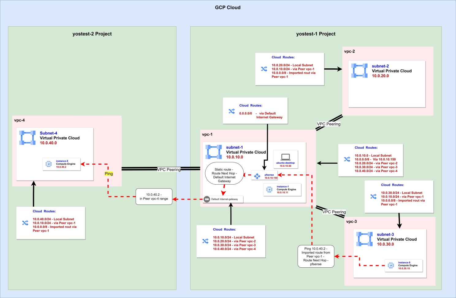
Now we can organize our cloud networks in a hub and spoke configuration. Traffic is routed as follows:
-
We have four networks.
-
At the center is pfsense with static routing that routes all internal network range 10.0.0.0/8 to the vpc-1 Gateway.
-
In vpc-1 there is routing of the entire internal network range 10.0.0.0/8 to pfsense.
-
Each of the other networks creates Peering with vpc-1 only.
-
The Peering includes export of routing from vpc-1 to the partner network.
-
The connecting network - say vpc-3 - receives the 10.0.0.0/8 routing to pfsense.
-
A machine in vpc-3 addressing a machine in vpc-3 or vpc-1 has more precise routing to the /24 network range, so routing is handled at the local level or through the Peer without needing the broader /8 range.
-
A machine in vpc-3 addressing a vpc-4 address finds no routing in the /24 ranges, so addresses the more general 10.0.0.0/8 routing, within which the vpc-4 range (10.0.40.0/24) is included.
-
From vpc-3 the routing goes through the Peer to pfsense.
-
Pfsense routes all 10.0.0.0/8 traffic via static routing to vpc-1’s Gateway.
-
The vpc-1 Gateway knows through Peering that the 10.0.40.0/24 range belongs to vpc-4, and directs the communication there.
-
The destination is in 10.0.40.0/24 and receives the communication.
The following diagram details the network structure, routing tables and traffic configuration:
 Hub and spoke configuration
Now let’s implement these settings to reach the same state as in the diagram.
Configuring the Gateway for the Internal Network:
-
In pfsense management under System, click Routing. On the page that opens there will be three tabs. Currently we’re in the Gateways tab. Now we only have the one for the external network.
-
Click Add to add an exit point for the internal network.
-
On the page that opens, enter the following data: Interface - LAN, Name - vpc1, Gateway - 10.0.10.1. Then scroll to the bottom, click Advanced and scroll to the bottom again, and mark Use non-local gateway.
- This is because in the machine’s internal DHCP configuration, its card is defined with Prefix 32, which means from its perspective the VPC’s Gateway seemingly sits on a different Subnet. Click Save.
Configuring Routes:
-
Switch to the middle tab - Static Routes.
-
The list is empty. We’ll add just one route. Click Add.
-
Fill in the following data: Destination network - 10.0.0.0, on the right will be the Prefix - choose 8. Gateway - select the one we just created, vpc1. Click Save.
-
Click Apply Changes.
Opening Traffic Across the Entire Internal Range:
-
Firewall >> Rules >> Add.
-
Change the following fields: Interface - LAN, Protocol - Any, Source - Network 10.0.0.0 /8, Destination - Network 10.0.0.0 /8.
-
Scroll down and click Save.
-
Click Apply Changes.
Hub and Spoke Architecture:
In the first lab we connected 3 networks using a Mesh network structure.
For connectivity from every VPC to every VPC, each VPC needed to send a Peering to each of the other networks. When it’s 3 VPCs, it’s not so bad. But what if there are more?
In such a case, networks are arranged in a hub and spoke structure. Due to GCP’s routing configuration, direct traffic transfer between two networks through the hub center isn’t possible. Peering only works to the directly connected network (second side), not to a network connected to it (third side). For that, a proxy is needed that sits in the central network and routes traffic to all other points. If that proxy is also a firewall, it gives additional control over traffic between networks - while allowing it technically but filtering it as needed.
We’ll make vpc-1 the hub center, and all other networks will connect to that same network. This way each network only needs to create a Peering to one network to connect to all other networks.
Connecting a Network to the Hub:
-
VPC network >> VPC networks >> vpc-2 >> VPC NETWORK PEERING.
-
Mark the vpc2-to-vpc3 connection and delete it. Now vpc-2 is only connected to 1, and vpc-3 is only connected to 1.
-
Go to VM instances and start instance-4 and instance-5. They both now sit in unconnected networks - we’ll use them to test connectivity.
-
Connect to both via SSH simultaneously.
-
From each of them, ping instance-1. Works. Both vpc-2 and vpc-3 are connected to vpc-1 after all.
-
From each of them, ping the other. Doesn’t work. Once the Peering was cancelled, there’s no connectivity.
-
Now go to Routes, and we’ll see we have one route in vpc-1 directing all 0.0.0.0 traffic to the default internet Gateway of that VPC.
-
Switch to the ROUTE MANAGEMENT tab.
-
Click CREATE ROUTE.
-
Fill in the following details: Name - to-pfsense, Network - vpc-1, Destination IPv4 range - 10.0.0.0/8, Next hop - Specify an IP address of an instance, Next hop IP address - 10.0.10.150.
-
Click CREATE.
-
Return to VPC network >> VPC networks >> vpc-1 >> VPC NETWORK PEERING.
-
Enter the Peering of each of the other networks, and verify the checkbox exporting internal address routing to the partner network is marked.
-
Try pings between instance-4 and instance-5. Works in both directions.
-
If it doesn’t work, enter the settings of vpc-2 and then vpc-3, and in each one’s peering settings against vpc-1, verify it’s configured to import internal address routes from the partner network - which in our case is vpc-1. Now it will work.
Quickly Adding a VPC to the Hub Structure:
If we want to add another network to the hub - even from another project - we can do so using a script.
The values we’ll need to enter in the script the first time will be four:
-
The Project ID of the project serving as the hub center.
-
The Project ID of the project wanting to join the hub structure.
-
The name of the network serving as the hub center - in our example vpc-1. Because this network contains the router address through which all traffic passes.
-
The name of the VPC wanting to connect to the hub.
For each additional network we want to add to the hub, we’ll only need to change the network name and Project ID of those joining.
So if we want to add vpc-4 from project yostest-2, we can use the following script:
$starproject = 'yostest-1'
$joineproject = 'yostest-2'
$joinenet = 'vpc-1'
$starnet = 'vpc-4'

gcloud compute networks peerings create to-star `
    --network $joinenet `
    --project=$joineproject `
    --peer-network $starnet `
    --peer-project=$starproject `
    --import-custom-routes

gcloud compute networks peerings create $joinenet.Split("/")[-1] `
    --network $starnet `
    --project=$starproject `
    --peer-network $joinenet `
    --peer-project=$joineproject `
    --export-custom-routes
And loops can always be used.
If we want to add all networks from a certain project to the hub, use the following configuration:
$starproject = 'yostest-1'
$joineproject = 'yostest-2'
$starnet = 'vpc-1'
$joinenet = gcloud compute networks list --project $joineproject --format json | ConvertFrom-Json | %{$_.name}

foreach ($x in $joinenet) {
    gcloud compute networks peerings create to-star `
        --network $x `
        --project=$joineproject `
        --peer-network $starnet `
        --peer-project=$starproject `
        --import-custom-routes

    gcloud compute networks peerings create $joinenet `
        --network $starnet `
        --project=$starproject `
        --peer-network $x `
        --peer-project=$joineproject `
        --export-custom-routes
}-
Don’t use the loop script if there is only one network in the project.
-
Note that the command has two parts. In one, the new network creates a connection with the central network and there’s a flag indicating to import routes from there. In the other, the central network responds to the new network and there’s a flag indicating to export routes to it.
-
All routing is defined in the central network. If there are additional ranges you want to route to such as 192.168.0.0 or 172.16.0.0, add the routing in vpc-1 toward pfsense, then in pfsense toward the Gateway. The joining network will import the routing from vpc-1 to pfsense, and from there everything will flow.
Firewall and Testing:
Now return to project yostest-2 and create an e2-micro machine in the Tel Aviv region in vpc-4, which we just added to the hub.
While the machine is being created and coming up, go to the firewall of the project and add two rules as we created them in the first project. One allows SSH connection from the range 35.235.240.0/20 to all machines in the network, the second allows traffic within the 10.0.0.0/8 range.
Now return to the VM Instances page and connect via SSH to the new machine.
Testing:
Ping to instance-1 - works.
Running the curl command http://10.0.10.11 to pull the content of the home page from the nginx server installed on instance-1 - works.
Now to a third-party network:
Ping to instance-5 - works.
We’ve created a hub and spoke topology.